Control Components
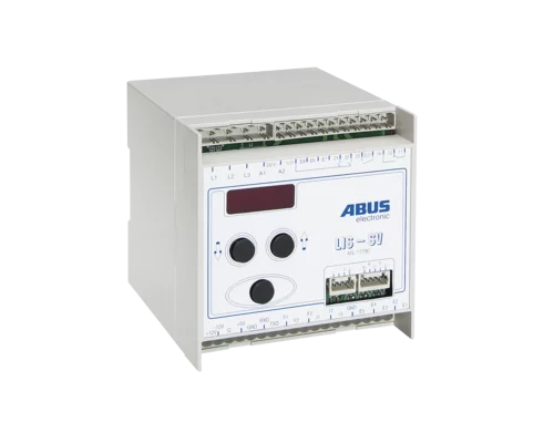
Central control system
The tried and tested multiple-standard design of ABUS control systems covers a wide range of applications. These are available in two different versions:
- The decentralised control system is sub-divided into separate panels on the crane bridge (SKR) and on the trolley (SKA).
- The centralised control system for the crane and the trolley is installed in a central position on the crane bridge.
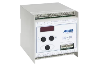
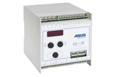
Load measuring system LIS
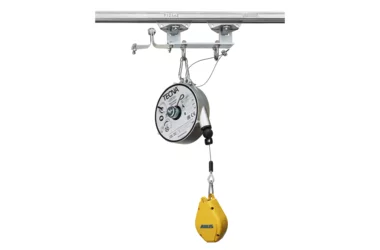
The ABUS double girder crane ZHB is our answer for heavy loads combined with area-coverage transport. The ZHB is also characterised by long crane spans. The ABUS chain hoist is also suspended between the crane girders making for an optimised lifting height.

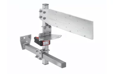
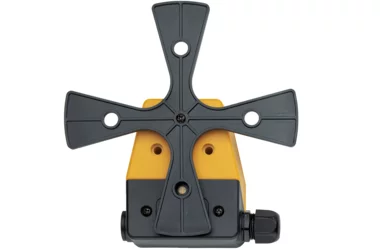
Cross-type limit switch
ABUS cross-type limit switch for electric limitation cause the automatic reduction or switching off of the travel movement of cranes and trolleys.
It can also be used for bypassing obstacles or blocked areas which the crane trolley is not permitted to travel over. Switching lugs on the track or the crane bridge actuate the cross-type limit switches.
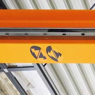
Operating direction signs
Safety when operating a crane is of utmost importance. ABUS uses operating direction signs so that the travel direction of the crane is always clear.
These signs are especially useful when the crane is being operated using a radio remote control. The symbols on the crane exactly match those on the radio remote control or pendant control so that it is clear which key must be used for the desired travel direction.
That's why the operating direction signs are included in the standard scope of delivery of ABUS overhead travelling cranes and are attached underneath the crane using magnets. This enables a later change in position or a retrofit and offers a significant benefit over conventional adhesive signs.
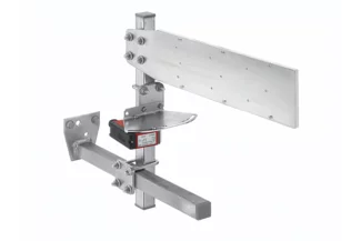
Anti-collision device
Does more than one crane travel on a crane track? Then we recommend installing a photoelectric anti-collision device. This protects the cranes from unintentional collisions.
This anti-collision device consists of two switching stages. A braking function reduces the speed of the crane to a slow speed as soon as there is the risk of a collision. In addition, there is the option of a shut-down. This brakes the travel movement to a complete stop. The switching distance can be infinitely adjusted on the reflective light barrier. The distance between the cranes can be up to 20 metres.
This photoelectric anti-collision device can also be used if two hoists travel on a crane or several hoists on a track.
Photoelectric anti-collision devices can also be used for building constructions or crane tracks which can only be used to a limited extent for static loads. However, safety must be further increased here. This is achieved by a light barrier system with a redundant design that has a check and failure indicator. This can prevent several cranes with full loads from being positioned in one track field.
